CA 02271402 1999-OS-10
to the suspension system 20. When the suspension system is at rest, the
vertical distance between
a top surface of the rear bumper 4 of the vehicle and the distal end of the
primary pivoting arms
64 is 19.892 inches. However, when the suspension system is active and at its
maximum
flexibility, the primary pivoting arms are in a relatively horizontal position
allowing for a vertical
clearance of at least 11.500 inches from the ground to the top surface of the
rear bumper 4 of the
vehicle. As is further illustrated in shadow lines in Fig. 4, track tension
creates a compression
of the rearward portion of the suspension system. The pulling belts are able
to pull down a front
portion of the chassis so that the rearwardly mounted travel means remain
generally horizontal
and remain in contact with the ground thereby maintaining good traction.
For purposes of completeness, the following is a chart of the angle of
displacement of the
primary pivoting arms 60, and the vertical distance from the distal end of the
primary pivoting
arms 60 to a top horizontal surface of the rear bumper 4 of the particular
land vehicle given in
this example:
An~le of Displacement (degrees Clearance (inches)
18.92 8.392
26.52 12.219
34.43 16.784
When the suspension system 20 is in full extension, the minimum angle of
displacement from
the distal end of the primary pivoting arm is 18.92 degrees, and when the
suspension system is
at rest, the maximum angle of displacement from the distal end of the primary
pivoting arm is
34.43 degrees.
The above description is of a generally centrally mounted rear suspension
system for a
land vehicle, such as a snowmobile. In an alternative embodiment, the
suspension system may
be in the form of a kit separate from the vehicle as a whole. The kit may be
assembled and
attached to a conventional snowmobile and used to modify an already existing
suspension
system.
-19-
CA 02271402 1999-OS-10
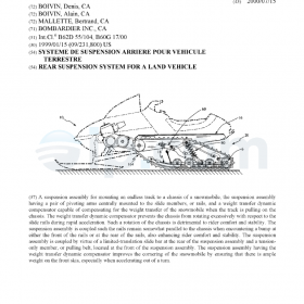
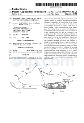
In the most preferred embodiment, a suspension assembly, designated
comprehensively
by the numeral 20, is able to mount an endless track 164 to a chassis 16 of a
snowmobile 10 as
best illustrated in Figures 14 and 15. While the suspension assembly 20 is, in
the most preferred
embodiment, attached to a snowmobile, such a suspension assembly could also be
adapted for
mounting to other types of tracked vehicles.
As shown in Figures 16-19, in the most preferred embodiment, the suspension
assembly
20 comprises two substantially parallel and spaced-apart elongated slide
members 18. The slide
members 18 are connected together by at least one transversely mounted bridge
member 70, 78.
The slide members 18 guide the endless track 164 and are commonly referred to
in the art as
« slide rails ». The slide members 18 are typically made of a light, rigid metal
such as aluminum.
The undersides of the slide members 18 are normally covered with a wear-
resistant polymer.
The slide members 18 often have a front portion that is curved upwards to
facilitate the traversing
of rough terrain.
In the most preferred embodiment, the suspension assembly 20 further comprises
two
substantially parallel and elongated pivoting arms 60, each having a first end
portion 64 pivotally
connected to said slide members 18 and a second end portion 62 adapted for
connection to the
chassis 16. The pivoting arms 60 are shaped so as to resist bending and to
minimize the
interference with other components of the suspension assembly 20 when the
suspension assembly
20 is compressed. In the most preferred embodiment, the pivoting arms 60 are
made of a light,
rigid material such as aluminum.
In the most preferred embodiment, the suspension assembly 20 further comprises
a rocker
arm assembly 120, 137 pivotally connected to said pivoting arms 60. The rocker
arm assembly
120, 137 has a first end portion 11 S pivotally connected to a substantially
rigid link 110. The
rocker arm assembly also has a second end portion 135 connected to a tension-
only member 130,
said tension-only member being connected to said slide members 18. The tension-
only member
130 is a linking member capable of withstanding only a tension load (i.e. it
cannot support a
compressive load). Some examples of tension-only members are ropes, cords,
belts and straps.
-20-
CA 02271402 1999-OS-10
In the most preferred embodiment, the suspension assembly 20 further comprises
a
resilient member 80 (also referred to as the primary suspension means). The
resilient member
80 is connected at a first end portion 82 to the chassis 16 and at a second
end portion 84 to the
slide members 18. When compressed, the resilient member 80 urges the slide
members 18 away
from the chassis 16. When the suspension is in static equilibrium, the
resilient force produced
by the resilient member 80 that urges the slide members 18 away from the
chassis 16 is
counterbalanced by the weight of the chassis and vehicle supported above it.
When the
suspension encounters bumps in the terrain, the resilient member 80 absorbs
and dissipates most
of the impact energy.
In the most preferred embodiment, the suspension assembly 20 further comprises
a slide
bar 150. The slide bar 150 has a first end portion 152 connected to the
chassis 16 and a second
end portion 154 slidingly engaged to a holder 170. The holder 170 is pivotally
mounted (at pivot
174) to a rear portion 19 of said slide members 18. The slide bar 150 is
capable of limited
1 S translation relative to said holder 170 by virtue of the washer 159 and
nut 1 SS on the threaded
end 157 of the slide bar 150. The slide bar 150 is thus restricted to move
within the internal gap
of the holder 170. Thus, the slide bar 1 SO limits the displacement of the
slide members 18
relative to the chassis 16.
Preferably, the resilient member 80 includes at least one spring 81. The most
common
and logical arrangement is to provide the suspension assembly 20 with two
identical,
symmetrically-disposed springs 81 in order to give the suspension assembly a
balanced and
stable response to impacts. More preferably, the resilient member 80 further
includes a damper
83. The damper 83 is advantageously arranged in tandem with each spring 81 as
illustrated in
Figure 17. The two symmetrical spring-damper units absorb and dissipate the
kinetic energy
imparted to the slide members 18 when the snowmobile 10 encounters a bump. The
quick and
controlled absorption and dissipation of the impact energy by the spring-
damper combination
maximizes comfort and handling. By varying the spring rate, damping ratio, and
geometry of
the shocks, the dynamic response of the suspension can be tailored from a
hard, « sport »
suspension to a softer, « touring » suspension. A suspension can have a « rising
rate » (the
stiffness of the springs increases as they are compressed) or a « falling rate »
(the stiffness of the
-21-
CA 02271402 1999-OS-10
springs is decreased as they are compressed) or a combination thereof (i.e.
the response of the
suspension varies as a function of the position and angle of the shocks).
Preferably, the tension-only member 130 is a pulling belt. The pulling belt is
capable of
limiting the upward motion of the rocker arm assembly 120, 137 away from the
slide members
18. The pulling belt thus restrains the front portion 15 of the chassis 16
during rapid
accelerations when the front portion of the chassis has a tendency to rise.
Preferably, the rocker arm assembly 120, 137 is integral with a tube 75a. The
tube 75a
may be permanently fixed to the rocker arm assembly by welding, soldering or
bonding
(depending on the materials used). In the most preferred embodiment, the tube
75a is welded to
the rocker arm assembly. Rotatable within the tube 75a is a shaft 75, shown in
Figure 16. The
shaft 75 is mounted transversely between the pivoting arms 60 by a threaded
fastener on either
end. The shaft 75 ensures that any tensile force generated by the pulling belt
130 is distributed
equally on both pivoting arms 60. Most preferably, the pulling belt is located
midway between
the pivoting arms to ensure an equal distribution of forces. However, the
pulling belt need not
be located midway in order for the suspension to function properly. The shaft
75 may also serve
as a cross-brace between the pivoting arms 60 to ensure that both pivoting
arms move in unison.
Preferably, the rocker arm assembly 120, 137 further comprises two rocker arms
120 and
137 mounted to the tube 75a in a transversely spaced-apart relation as shown
in Figure 16. The
rocker arms are angled with respect to one another (as seen in the plane
defined normal to the
axis of the tube 75a, i.e. in the plane shown in Figures 17-19). The rocker
arms 120 and 137 are
welded to the tube 75a. As will be shown below, other rocker arm
configurations are also
possible as indeed are other methods of rigid attachment.
In a second variant, instead of two distinct rocker arms, the rocker arm
assembly
comprises a unitary, generally L-shaped rocker arm 137 as shown in Figure 21.
This
arrangement is similar to the previous variant except that the arms of the
rocker are not
transversely spaced-apart. The second variant functions almost identically to
the first variant
shown in Figures 16-19. The generally L-shaped rocker arm 137 is pivotally
mounted to the
-22-
CA 02271402 1999-OS-10
tube 75a and pivotally connected to the rigid link 110 at pivotal end 115. The
generally L-
shaped rocker arm is also connected to the pulling belt 130. If the pulling
belt 130 is again
located midway between the pivoting arms 60, then the rigid link 110 will be
also located
midway between the pivoting arms. To locate the rigid link midway between the
pivoting arms,
the middle idler wheel on the first transverse member 40 would need to be
displaced to allow the
rigid link to attach to the first transverse member 40. Alternatively, the
rigid link could have a
forked end so that the rigid link attaches to the first transverse member 40
at two attachment
points on either side of the middle idler wheel.
In a third variant, the rocker arm assembly comprises a pulley 139 around
which the
pulling belt 130 is partially wrapped as shown in Figure 22. The pulley 139 is
connected to a
rocker arm 120. When the pivoting arms 60 move upwards, the pulley 139 rotates
making the
pulling belt taut. When the pulling belt is taut, the tensile force of the
pulling belt 130 limits the
upward movement of the front portion 15 of the chassis 16.
A fourth variant is illustrated in Figure 23 in which the rocker arm assembly
comprises
a pulley 139 around which the pulling belt 130 is partially wrapped. In the
variant of Figure 23,
the pulling belt is partially wrapped around the rear-facing side of the
pulley 139 as opposed to
the front-facing side of the pulley as was the case in Figure 22. In Figure
23, the rocker arm 120
is oriented toward the front portion 15 of the chassis 16 whereas, in Figure
22, the rocker arm
120 is oriented toward the slide members 18.
A fifth variant is illustrated in Figure 24 in which the rocker arm assembly
comprises a
generally linear rocker arm 120. In Figure 24, the rocker arm 120 is pivotally
connected to the
tube 75a around shaft 75. The pulling belt 130 is connected to one end of the
rocker arm 120.
The rigid link 110 is connected to the rocker arm 120 at the pivotal end 115.
A sixth variant is illustrated in Figure 25 in which the rocker arm assembly
comprises a
generally L-shaped pulley-like member 137 capable of exerting a tensile force
on said pulling
belt 130. The generally L-shaped pulley-like member 137 is pivotally mounted
to the shaft 75
and connected to the rigid link 110 at pivotal end 115. The pulling belt 130
is mounted to the
-23-
CA 02271402 1999-OS-10
front-facing surface of the L-shaped pulley-like member 137. When the L-shaped
pulley-like
member 137 rotates, the pulling belt becomes taut thereby exerting a
restraining force on the
pivoting arms 60 which tends to limit the upward movement of the front portion
15 of the chassis
16.
For any of the foregoing variants, the suspension assembly 20 may further
comprise a
second tension-only member 131 connected at one end to said rocker arm
assembly 120,137 and
connected at a second end to said slide members 18 via a transverse member 78.
The second
tension-only member functions in precisely the same manner as the first
tension-only member
(i.e. the pulling belt 130). The second tension-only member 131 is simply a
backup member that
limits the upward movement of the front 15 of the chassis 16 in case the
pulling belt 130 breaks.
The second tension-only member 131 is preferably a limiting strap made of a
tough, light
material such as nylon or reinforced rubber.
1 S In any of the foregoing variants, the resilient member 80 and the rigid
link 110 may be
connected to a first transverse member 40, the transverse member 40 being
connected to the
chassis 16. The first transverse member 40 is preferably made of steel,
aluminum or an alloy
and is rigid enough not to deflect or deform substantially under the loads
imposed upon it by the
chassis 16, the resilient member 80, the slide bar 150 and the rigid link 110.
Similarly, in any of the foregoing variants, the second end portion 62 of the
pivoting arms
60 may be connected to a second transverse member 50, the second transverse
member being
connected to the chassis 16 at the front portion 15. The transverse member 50
is preferably a
hollow shaft made of steel or aluminum and which is disposed with two flanges
welded thereto.
The flanges are provided with holes for fastening to the pivoting arms 60. The
transverse
member should be rigid enough to withstand all loads imposed on it by the
chassis and pivoting
arms without substantial deformation.
In operation, the suspension assembly 20 functions firstly to absorb and
dissipate impact
energy transmitted to the suspension assembly while traversing rough terrain
and, secondly, to
compensate for the weight transfer induced when the engine is pulling on the
track.
-24-
CA 02271402 1999-OS-10
In the latter case, when the snowmobile 10 undergoes rapid acceleration, the
engine pulls
on the track, thereby putting a portion of the track into tension. This
tensile force creates internal
reactions which cause the rear of the chassis to dip and the front 15 of the
chassis to rise. Thus,
when viewed from the left side as in Figures 17-25, the chassis tends to
rotate in a clockwise
direction. When the front of the chassis rises and the acute angle between the
pivoting arms 60
and the slide members 18 increases, the second transverse member (shaft 50)
rises with respect
to the first transverse member (shaft 40). Since both members 50 and 40 are
fixed to the chassis,
the distance between them necessarily remains the same. However, since the
shaft 75 is rigidly
attached to the pivoting arms 60, the distance between the shaft 75 and the
first transverse
member 40 diminishes. As the shaft 75 nears the first transverse member 40,
the rigid link 110
exerts a force on the rocker arm 120 at the pivotal end 115 causing the rocker
arm 120 and hence
the tube 75a to pivot about the shaft 75 in a clockwise orientation (again as
viewed from the left
side). The clockwise rotation of the tube 75a about the shaft 75 also causes
the rocker arm 137
to rotate about the shaft 75. The rotation of the rocker arm 137 causes the
second end portion
135 to rise with respect to the slide members 18. As the second end portion
135 rises, the pulling
belt 130 becomes taut, as shown in Figure 20, thereby precluding any further
upward movement
of the front portion 15 of the chassis 16. Thus, during rapid accelerations,
when the front
portion 15 of the chassis 16 tends to rise due to track tension, the
suspension assembly
counteracts the weight transfer by restraining the front portion 15 of the
chassis 16 from further
elevation.
When traversing bumpy terrain, the suspension assembly 20 absorbs impacts and
ensures
that the rails (i.e. slide members) remain essentially parallel to the
chassis. In the foregoing
analysis of the suspension’s weight transfer dynamic compensation, the slide
members were
treated as if they remained on the ground at all times and the chassis moved
with respect to the
slide members. When considering the suspension’s response to a bump, the point
of view is
reversed: the chassis can be treated as being somewhat fixed while the rails
move.
A bump acting at the rear of the slide members produces essentially the same
relative
response as the weight transfer dynamic compensation described above. In other
words, the rear
of the slide members moving toward the rear portion of the chassis is
essentially equivalent to
-25-
CA 02271402 1999-OS-10
the rear of the chassis dipping toward the rear of the slide members. The
suspension, being
coupled, will react by lifting the front of the slide members so that the
slide members rise in a
substantially parallel manner. When the bump acts on the rear of the slide
member 18, the slide
members rotate counterclockwise as shown in Figure 33.
This rear bump compresses the resilient members 80 and causes the slide bar
150 to
translate within the holder 170 such that the nut 155 moves toward the surface
176. Due to the
counterclockwise rotation of the slide members 18, the acute angle between the
pivoting arms
60 and the slide members 18 increases until the pulling belt 130 becomes taut.
The slide
members 18 are thus limited from further counterclockwise rotation. The front
and rear of the
suspension are coupled and any further compression in the form of a
counterclockwise rotation
of the suspension necessarily compresses the resilient members 80. The slide
members 18
remain substantially parallel to the chassis once the suspension is coupled.
1 S Another way to visualize the effect of a rear bump is to imagine a bump
propagating
under the slide members moving from the front of the slide members toward the
rear. When the
bump is exactly midway along the slide members, as shown in Figure 32, the
suspension is in
its « ideal posture » because the slide members are instantaneously parallel to
the chassis and to
the ground. Then, when the bump moves toward the rear, the front of the slide
members drop.
This dropping of the front of the slide members amounts to a counterclockwise
rotation which
causes the angle between the pivoting arms 60 and the slide members to
increase until the pulling
belt 130 become taut enough to preclude any further counterclockwise rotation
of the slide
members. The suspension is thus coupled.
A bump acting at the front of the slide members causes the slide members to
rotate
clockwise as shown in Figure 31. As the rear portion 19 of the slide members
drops, the distance
between the pivot 174 (of the holder 170) and the first transverse member 40
diminishes until
the washer 159 and nut 155 abut the holder 170. In other words, the slide bar
slides in the cavity
172 of the holder 170 until the washer 159 and the nut 155 collide with the
inner surface of the
holder. At that point, as shown in Figure 31, the suspension becomes coupled.
The slide
members 18 are no longer able to freely rotate clockwise. Any further attempt
to rotate the slide
-26-
CA 02271402 1999-OS-10
members clockwise is resisted by the resilient members 80. With the slide bar
150 abutting the
holder 170, the suspension is coupled and the rear of the slide members will
then rise with the
front of the slide members. Thus, the slide members remain substantially
parallel to the chassis
when encountering a bump on the front of the slide members.
In summation, the rocker arm assembly 120, 137, pulling belt 130 and rigid
link 110
function collectively as a Weight Transfer Dynamic Compensator (« WTDC »). The
WTDC is
essentially a mechanical chain linking the slide members 18 to the chassis 16.
The six variants
described above illustrate that there are numerous ways to implement a WTDC.
In all of the
variants, there is a tension-only member that is activated by a pivotal or
rotational movement
governed by the pivoting arms.
The WTDC compensates dynamically for the weight transfer of the snowmobile
that
arises when the engine is pulling on the track. A snowmobile with a WTDC is
not only more
comfortable to ride during rapid acceleration but it maintains better ground
contact. When the
weight on the front skis is diminished (as a direct result of weight
transfer), the steering capacity
is commensurately reduced. Thus, the WTDC ensures that even though the
snowmobile is
undergoing rapid accelerations, there is still enough weight on the front skis
to permit proper
steering of the snowmobile. This enhances cornering performance since the
snowmobile rider
is able to steer and accelerate concurrently.
Although the present invention has been described in connection with preferred
embodiments thereof, it will be appreciated by those skilled in the art that
additions, deletions,
modifications, and substitutions not specifically described may be made
without departing from
the spirit and scope of the invention as defined in the appended claims and
the scope should not
be limited to the dimensions indicated hereinabove.
-27-


 English